Basic Implementation
The maze generator is in javascript and it’s producing a Json file that looks like this:
There’s some extra data, because I’m saving the cell’s coordinates as both the dictionary key and in the x and y values, but that’s mostly just for readability. I throw the keys away immediately, because I only need the values.
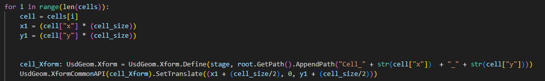
We then take that list of cells and, iterating through them, we find the corner locations, and use them plus half a cell to find the centre location, which I place a parent transform at.
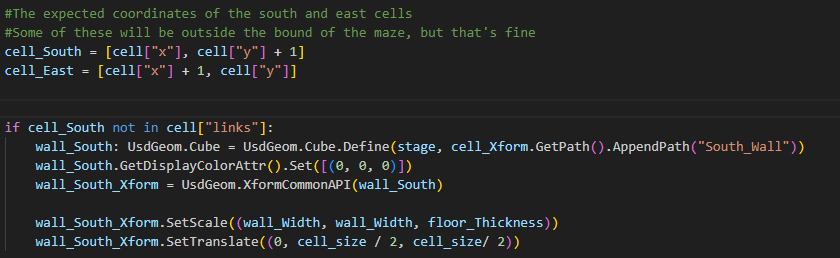
Then, we test if the coordinates for a neighbour cell are in the linked cells list, if they aren’t, we would like to place a wall. We only make the north or west walls if we're at the edge of the maze (as in, the x or y positions are 0), to avoid duplicate geometry.
When I first tried to do this, I got far too many walls and a strange diagonal line through the middle. Using some print statements, I was able to find out that only connections with symmetrical coordinates ([0, 0], [1, 1], [5, 5]) were being correctly processed, and it was because I got X and Y mixed up earlier in the code.
Once we’ve identified that we want to place a wall, it’s just a matter of creating a cube of the correct dimensions and moving it to the right place.
I’ve had some issues with z-fighting on corners and there’s two ways I could solve them. On the one hand, I could change the system to be creating an entire solid mesh out of the maze by defining vertices. That would preclude arbitrary meshes though, and I think those are more useful for games. Instead, when I upgrade this to use arbitrary meshes, I’ll ask the user for a corner mesh, which will make the maze overall more interesting too.